Table of Contents
Definition:
A series of resistive elements which, when tapped at any point in between, produces a fraction of the voltage applied between its ends, is defined as a voltage divider network.
What is a Voltage Divider Network?
A voltage divider network basically distributes the input voltage among the components of the divider.
This concept is mainly used in circuits when the components operate on voltages lower than the supply voltage. So we scale down the voltage using a voltage divider network.
Practically, this circuit is available as a ‘pot’ or potentiometer.
The components of the divider are passive in nature i.e they do not generate energy in the circuit. The simplest example of a passive element is a resistor. Other examples include capacitors, diodes and inductors.
You might have seen a voltage divider in many common circuits. For example, in the circuitry of an IR sensor. Learn more about IR sensors here
What does a Voltage Divider Network look like?
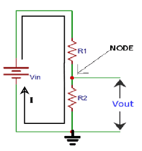
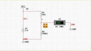
Resistors R1 and R2 are connected in series and a power supply Vin is applied across the combination. According to Kirchhoff’s Voltage Law there will be a potential drop across each of the resistors. The output voltage is available across R2.
As mentioned above, we use it to get a lower voltage to operate some device. For this, connect the positive terminal of your target device at the node in between the two resistors. Connect the negative terminal to the common ground. Then Vout will be the voltage drop across your device.
Equation Explanation:
The voltage divider equation is given by:
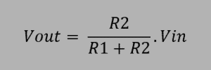
When a current flows through 2 or more resistive elements connected in series, there is a voltage drop across each element. This is according to Ohm’s law which states that the voltage drop is proportional to the current as well as the resistance: V= IR.
Let current through R1 be I1. And the current through R2 be I2.
Voltage drop across R1 is V1= I1R1
Voltage drop across R2 is V2= I2R2 ………(1)
So by Kirchhoff’s voltage law or loop equation , the total voltage drop is equal to the supply voltage:
V=I1R1 + I2R2 .
But actually the current flowing through a series circuit is the same in all the elements!
So, I1=I2
Therefore, V= I (R1+R2)
or , I=I2= V/(R1+R2) ……….(2)
Substituting equation (2) in (1),
which is the voltage divider equation. Here, V2=Vout i.e the output voltage. And V is Vin i.e the supply voltage.
Examples
Let us now look into some examples of voltage calculation in a Voltage Divider Network.
Example 1
Consider a supply voltage of 5V, i.e Vin = 5V
Let R1=1kΩ, R2=10kΩ
The output voltage Vout is given by:
Example 2
Now suppose we want a voltage range of 0.5 to 4V at the output. You can get this by adjusting the resistor values. It’s easier to use a rheostat or variable resistor in the physical circuit.
For Vout = 0.5V, assuming a Vin of 5V,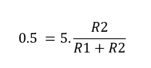
Keeping R1 constant (for eg: 1k) you can vary R2 .
Suppose R2 is 100 ohm.
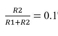
Similarly if Vout = 4V then R2/R1+R2 = 4/5
So the ratio must stay 0.8 while you vary R1 and R2. It’s better to keep R1 constant. If R1 is 1k then R2 will be 4k.
Proteus Simulation of Voltage Divider Network
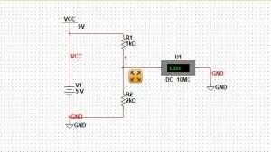
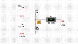
To construct a voltage divider in Proteus simulation, just apply a voltage across two resistive elements and take an output from the node in between the two resistors.
You will find that there has been a voltage drop across the first resistor. And depending on the value of the second resistor, the voltage reading on the potentiometer will vary as shown in the simulation images given below:
The input voltage in all three cases is 5V, but depending on the value of the resistances involved the voltage gets scaled down.
Download Proteus Demonstration software for free here:
https://www.labcenter.com/downloads/
Applications Voltage Divide Network:
A potentiometer is the most common circuit that uses voltage division in its operation. Some applications are:
- Volume control knobs in radios are basically potentiometers.
- For adjusting the level of a signal, for bias of active devices in amplifier.
- To measure the resistance of a sensor, in order to feed it to a microcontroller.
- To scale down a very high voltage so that it can be measured by a voltmeter. (Capacitive divider probes are typically used for voltages above 100 kV due to excessive heating and power loss in ordinary resistors).


