Table of Contents
A Line Follower Robot uses Infrared sensors to sense a black line or a white line. This post explains the logic used to configure a line follower. An embedded C program along with the full code is also given as an example for simulation on Proteus Turtlebot.
Working logic:
A line follower typically has 3 IR sensors. Check out how IR sensors work here:
https://nerdyelectronics.com/embedded-systems/sensors/ir-sensor-module/
In the Proteus simulation turtlebot, when following a black line on white background, the sensor LED glows when it detects a black line. This may seem weird if you have read the IR sensor post above, but it depends on where the photodiode is connected.
IR sensors detect full reflection or white suface as 1 and no reflection or black surface as 0. The digital output of the IR sensor is connected to the indicator LED. But it is a feature of the turtlebot that when IR digital output pin reads LOW, it is inverted to read HIGH on the LED.
So though your sensors detect 1,0,1 i.e black line in the centre, the LEDs glow in the pattern 0,1,0 and 0,1,0 is fed to the microcontroller.
It can be confusing at the start but don’t worry you’ll get the hang of it soon. Basically the lights on the Turtlebot indicate presence of black line. If an LED is glowing, black line is present under it. If it is not glowing, black line is not present under that LED.
Case 1: Black line is in the middle. Middle LED glows
Case 2: Black line is at the left. Left LED glows
Case 3: Black line is at the right. Right LED glows
Case 4: Black line not detected. All LED’s are dark
Case 5: Entire surface is black. All LED’s glow

Motor movement:
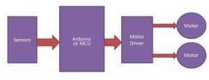
You can manipulate each function i.e direction and speed by setting or resetting the corresponding bits in the appropriate register. Bitwise operators are use for this in the embedded C code given below. The bits in the registers are labelled according to their functions. For example if RF pin is set to 1, it means Right motor will move Forward. Similarly if LB pin is set to 1, Left motor will move Backward.
Code :
Here is a project in embedded C for a basic line follower using ATmega 328P. You can execute it in a Proteus demonstration Turtlebot simulation .Just load the .hex file or .elf file from the folder. The entire code for simulating a line follower on Proteus is given below: https://github.com/bhageria/nerdyelectronics/tree/line_follower/line_follower You must remember to copy paste the .hex file here into the simulation Arduino and delete the original .hex file. Since you are using Proteus demonstration, this won’t do any harm. Download the free Proteus demonstration simulation software here: https://www.labcenter.com/downloads/ The code snippets from the same file, required to understand the logic are given below:
Black line follower
The algorithm detects a black line on a white surface and the robot take turns accordingly. Here sensor status in the if statement means indicator LED status of the bot.
void follow_black_line(void)
{
		    while(1){
			     motors_move_forward();
			     read_line_sensor();
			     if(!left_status && center_status && !right_status)		//0,1,0
			     {
				     motors_move_forward();
				     set_duty_cycle(200,200);
				     _delay_ms(100);

			     }
			     if(left_status && !center_status && !right_status)		//1,0,0
			     {
				     soft_left();
				     set_duty_cycle(0,200);
				     _delay_ms(50);

			     }
			     if(left_status && center_status && !right_status)		//1,1,0
			     {
				     soft_left();
				     set_duty_cycle(0,200);
				     _delay_ms(50);

			     }
			     if(!left_status && !center_status && right_status)		//0,0,1
			     {
				     soft_right();
				     set_duty_cycle(200,0);
				     _delay_ms(50);

			     }

			     if(!left_status && center_status && right_status)		//0,1,1
			     {
				     soft_right();
				     set_duty_cycle(200,0);
				     _delay_ms(50);

			     }
			     if (!left_status && !center_status && !right_status)	//0,0,0
			     {
				     motors_move_backward();
				     set_duty_cycle(100,100);
				     _delay_ms(5);
				     //stop();

			     }
				if(left_status && center_status && right_status)		//1,1,1
				{
				    stop();
				}
		}
}
You may notice some functions like motors_move_forward , set_duty_cycle , read_line sensor, soft_left etc. in the code snippet above. These functions do exactly as they say. They are self-descriptive. Just understand the logic for now. The complete functions and related register pin macros are given in the code in the github link:
https://github.com/bhageria/nerdyelectronics/tree/line_follower/line_follower
White line follower
Similarly, for white line on black background, the middle LED will be dark when turtle is centred on the white line. The LED status will be 1,0,1. So you must move the wheels accordingly.
To follow a white line on a black background, the logic is as follows:
void B_W_B (void)	//Code for traversal on White line on Black Background
{
	  while(1){
		  motors_move_forward();
		  read_line_sensor();
		  if(left_status && !center_status && right_status)		//0,1,0
		  {
			  motors_move_forward();
			  set_duty_cycle(200,200);
			  _delay_ms(100);

		  }
		  if(!left_status && center_status && right_status)		//1,0,0
		  {
			  soft_left();
			  set_duty_cycle(0,200);
			  _delay_ms(50);

		  }
		  if(!left_status && !center_status && right_status)		//1,1,0
		  {
			  soft_left();
			  set_duty_cycle(0,200);
			  _delay_ms(50);

		  }
		  if(left_status && center_status && !right_status)		//0,0,1
		  {
			  soft_right();
			  set_duty_cycle(200,0);
			  _delay_ms(50);

		  }

		  if(left_status && !center_status && !right_status)		//0,1,1
		  {
			-  soft_right();
			  set_duty_cycle(200,0);
			  _delay_ms(50);

		  }
		  if (left_status && center_status && right_status)		//0,0,0
		  {
			  motors_move_backward();
			  set_duty_cycle(100,100);
			  _delay_ms(5);
			  //stop();

		  }
		  if(!left_status && !center_status && !right_status)		//1,1,1
		  {
			  stop();
		  }
	  }
}
On an Arduino, when the IR module’s analog output pin is connected to analog input of your Arduino, numbers in the range 0 to 255 (8-bit data) are displayed on your serial monitor, with
0== Black / no object /no reflection of IR
255 == White / object is nearest/ full reflection of IR.
Applications:
- A lot of industries use Line Follower Robots for automating the tasks such as retrieval and deposition of materials and heavy goods. The shop-floor has lines printed on it for the robot to follow. The robot follows the path according to the code fed into it. To avoid obstacles it uses sensors such as ultrasonic or infrared. https://www.youtube.com/watch?v=zNMvqSGCb4M
- Restaurants are increasingly using Line Follower Robots as waiters and waitresses. Check out a cool video here: https://www.youtube.com/watch?v=3OgFZovYS9U




Thanks for this amazing article , I benefited a lot.
I just will be very grateful if you share with me the proteus simulation project , so I can one it on the software (proteus).
Thanks 🙂 😀
Hi
You can find it here: https://github.com/bhageria/nerdyelectronics/tree/line_follower/line_follower