Table of Contents
GPIO, General Purpose Input Output is a set of pins in the microcontroller, which functions by passing data into and out of the board. They serve as a bidirectional pin, either as an input or output pin, or it also serves as an alternate functionality pin.
- When serving as input, it brings information into the board from an input device to the processor on the micro-controller board.
- When serving as an output pin, the data from the board is transferred to an output device from the processor.
- The alternate functionality can include for the pin being used as either a USART transmit pin or an SPI MOSI pin etc. This can be selected from the GPIOx_AFR register (depending on the board specs).
The popular examples include Blinking LEDs and the use of PUSH buttons. It is also used to issue interrupts, reading digital signals, waking up the processor, etc.
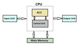
The Fig.1. Shows a general block diagram of microcontroller, where it consists of a master processor, I/O pins and memory unit. The Fig.2. Shows the pin diagram of STM32407VGTx containing 100 pins (LQFP100 package).
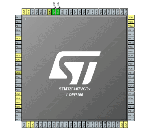
Generally, a set of GPIO pins form a GPIO port represented as GPIOx, for eg: GPIOA. GPIO ports of various microcontrollers have different sizes, for eg., 8051 based boards support 8 I/O pins, STM32 based boards support 16 I/O pins. These 16 pins form a port, hence it can be said that a GPIO port in STM32F4xx is 16-bit wide and each pin corresponds to a particular bit in the GPIO port registers. STM32F4xx board contains 11 ports from GPIOA to GPIOK, each having its own register set. These ports are configured for specific modes which are discussed later.
Features of GPIO
- Output states supports push-pull or open-drain + pull-up/down.
- Speed selection for each I/O.
- Input states can be configured as floating, pull-up/down, analog
- Locking mechanism (GPIOx_LCKR) is provided to freeze the port A or B I/O port configuration.
- The flexibility of selecting alternate functionality.
- Fast toggle capable of changing every two clock cycles
- Highly flexible pin multiplexing allows the use of I/O pins as GPIOs or as one of several peripheral functions.
How does GPIO work internally?
Basically a GPIO pin consists of an input buffer, an output buffer and an ENABLE pin. The value provided at the ENABLE pin decides whether the GPIO would work either as an input or an output.
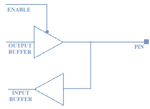
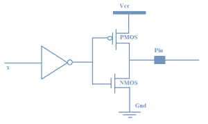
The internal circuitry of the buffer is a simple CMOS logic circuit. It has a PMOS transistor connected to the +Vcc and an NMOS transistor connected to the ground as shown in fig. 4. When the ENABLE pin set to 0, the output buffer is enabled and when it is set to 1, the input buffer is enabled.
ENABLE.[0] = 0 – The Pin functions as OUTPUT pin.
ENABLE.[0] = 1 – The Pin functions as INPUT pin.
Working:
For OUTPUT function: The ENABLE pin is set to 0, after passing the inverter logic it is set to 1, due to which the PMOS transistor is disabled and the NMOS transistor is enabled pulling the pin to GND (state LOW).
For INPUT function: The ENABLE pin is set to 1, after passing the inverter logic it is set to 0, due to which the NMOS transistor is disabled and the PMOS transistor is enabled pulling the pin to +Vcc (state HIGH).
Whenever the board is powered ON the GPIO pins, are by default in INPUT state i.e. they are in a HIGH impedance state. This is done to keep the system safe.
GPIO Modes
As we have already seen, the GPIO can be configured either to send data from the processor to an output device or receive data from an input device and send it to the processor. But most of the GPIO’s in microcontrollers support additional functionalities; they function as an I/O pin of other peripherals for eg. Tx pin UART, MOSI pin of SPI, etc. This feature of the controller is called Alternate functionality. The ability to exhibit different functionality by the GPIO is referred to as GPIO modes.
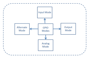
Similarly, GPIO pins in the STM32F4xx controller can be configured for 4 types of GPIO modes which are:
- Input Mode:
- Output Mode
- Analog Mode
- Alternate function Mode
Input Mode
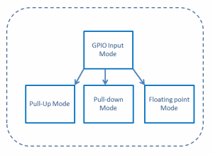
In input mode, the data is received from an external input device (sensor) and is converted to the digital format by an ADC (Analog to digital converter), which is sent to the master processor for further processing. The input mode in STM32F4xxx can be configured for 3 configurations which are:
- Pull-Up
- Pull-down
- Floating point
Whenever a pin is configured as input the following characteristics are exhibited:
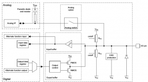
- The output buffer is disabled as shown in the fig.7
- The Schmitt trigger input is activated.
- The pull-up or pull-down resistors are activated depending on the value in the GPIOx_PUPDR register.
- The data present on the I/O pin is sampled into the input data register at each AHB clock cycle.
- The I/O state is obtained by reading the GPIOx_IDR input data register.
Floating point:
This state is called a HIGH impedance state, indeterminate state or high Z-state wherein the pin toggles between HIGH and LOW induced by the external noise. Here basically the pin is not connected to either to the +Vcc or the GND. Whenever a GPIO pin is not in use, it is basically in an input state with a High Impedance state. It is recommended to keep the unused pins in either pull-up or pull-down state to avoid leakage of current.
To avoid this HIGH impedance state, a pull-up or a pull-down register is introduced. Let us see what is the pull-up/pull-down configuration.
Pull-Up:
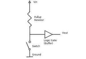
If the input is configured for internal pull-up, then the state will be HIGH unless an external pull-down register is used. This avoids the HIGH impedance state. The Fig.8. shows the pull-up register connected to the input buffer.
Pull-down:
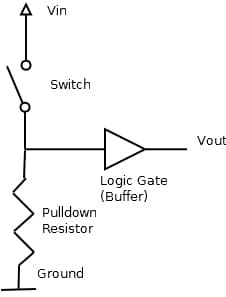
If the input is configured for pull-down, then the state will be LOW unless an external pull-up register is used. This avoids the HIGH impedance state. The Fig.9. Shows the pull-down register configuration.
Output Mode
Whenever the transistor is switched ON, the NMOS is active and hence the output will be pulled to LOW. And when the transistor is switched OFF, the NMOS is inactive making the drain of the transistor to be in the floating state. Hence the name, OPEN DRAIN. There are two configurations:
- Push-Pull and
- open drain.
The selection of the mode can be done using the GPIOx_OTYPER register. Fig.10 shows the configuration of Output Mode.
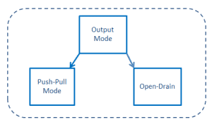
An output configuration of the pin exhibits the following characteristics:
- The output buffer can be configured in open-drain or push-pull mode as shown in fig. 7.
- The Schmitt trigger input is activated
- The internal pull-up and pull-down resistors are activated depending on the value in the GPIOx_PUPDR register.
- The written value into the output data register GPIOx_ODR sets the I/O pin state
- The written data on GPIOx_ODR can be read from the GPIOx_IDR register that is updated every AHB clock cycle.
Push-Pull:
Here in this configuration, both NMOS and PMOS are ON/OFF to drive the output at an appropriate level. The top transistor (PMOS) is ON when the output has to drive HIGH state. The bottom transistor (NMOS) is ON when the output has to drive a LOW state. Push-pull mode is the default mode in output configuration.

Open drain:
In this configuration, as shown in fig.12. The PMOS transistor is not present, making the output to be in high impedance state. This state is useless until a pull-up resistor either internal or external.
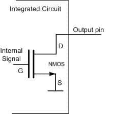
The open-drain output is often used to control devices that operate at a different voltage supply than the STM32. An open-drain mode is also used to drive one or several I2C devices when specific pull-up resistors are required.
Analog Mode
In analog mode, it allows the use of peripherals including DAC, ADC, OP-AMP, etc. GPIOx_ASCR to select the required function ADC, DAC, OPAMP, or COMP
When the I/O port is programmed in an analog configuration:
- The output buffer is disabled
- The Schmitt trigger input is deactivated, providing zero consumption for every analog value of the I/O pin. The output of the Schmitt trigger is forced to a constant value (0).
- The pull-up and pull-down resistors are disabled by hardware
Alternate functionality mode
GPIO pins have the capability of to provide an alternate function apart from the regular three modes. The pins are multiplexed to provide functionalities like USART Tx pin, I2C data pin, etc. The selection of the function can be done by configuring the GPIOx_AFRL (for pin 0 to 7) GPIOx_AFRH (for pin 8 to 15).
When the I/O port is programmed as alternate function mode:
- The output buffer can be configured in open-drain and push-pull mode
- The output buffer is driven by the signals appearing from the peripheral (transmitter enable and data)
- The Schmitt trigger input is activated
- The pull-up and pull-down resistors activations depend on the value in the register GPIOx_PUPDR.



Re: GPIO pin in Output mode. Can it tolerate a short to ground?
Generally, it can’t. However, you need to refer to the datasheet for more details. If they have short circuit protection, your pin can survive.
while some microcontrollers can tolerate brief shorts to ground due to built-in protection, it’s generally best to avoid such situations and use external protection to safeguard your hardware.