
Table of Contents
Are you working on a project that has two different voltage levels? Maybe an Arduino interfacing with the ESP8266 Wifi Module? Or just a microController running at 5v interfaced with the ESP8266? If yes, then you might have realized that you cannot interface both the systems directly. Fortunately, there is an easy solution to this problem. The bi-directional logic level converter. It is used to convert signals from 5v to 3.3v and vice-versa.
So, using the module, you can now easily connect the UART pins of the ESP8266 and the arduino or another microcontroller.
The bi-directional logic level converter is a very simple board that provides hassle free interface between systems operating on two different voltage levels.
Why do we need the 5v-3.3v Bi-Directional Logic Level Converter
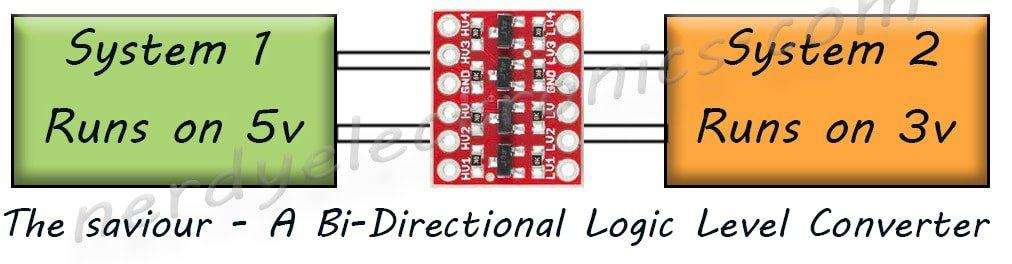
Lets take an example to understand the problem and the solution. Say there are two systems where system 1 works on 5 volts and system 2 works on 3 volts. So, all the high-output signals from system 1 will be at 5 volts and all the high-output systems from system 2 will be at 3 volts. Same goes for input signals. System 1 expects 5 volts and system 2 expects 3 volts.
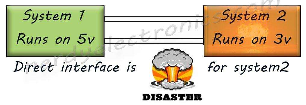
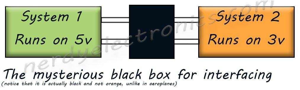
While this might not seem to be a huge problem, in reality it is. It is dangerous particularly for system 2. The high voltage might deliver more current than the tolerance limit of system 2 and damage it. We need an interface between the two systems. An interface that will convert 5 volts signals from system 1 to 3 volts for system 2 and 3 volts signals from system 2 to 5 volts for system 1.
Although many people use a resistor based voltage divider network to get this job done, it is not a good solution. The resistor network is like this-
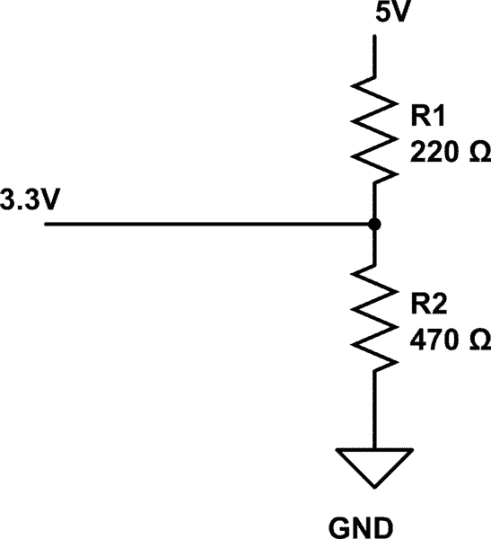
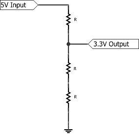
Can you see the problem here? The resistor values have to be recalculated every time there is change in voltage levels of any of the two or both systems. There is one other problem. While you can convert a higher voltage level to a lower one, you can’t do the reverse of it, i.e., You can convert say 5 volts to 3 volts but not 3 volts to 5 volts using this method.
The solution – A Bi-Directional Logic Level Converter
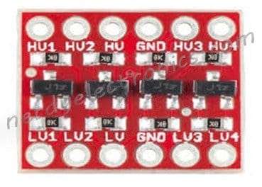
The Bi-Directional Logic Level converter is exactly what we need. In the image above, you can see the organization of the pins. One side is the high voltage (HV) side and the other side is the low voltage (LV) side. The signals from system 1 in our example connect on the HV side and the signals from system 2 connect on the LV side.
The working of the 5v-3.3v Bi-Directional Logic Level Converter
The working of the Bi-Directional Logic Level Converter is preety simple. We first have to define the two voltage levels. In our example, the HV is 5v and the LV is 3v. So, we have to connect the HV pin on the HV side to 5v and the LV pin on the LV side to 3v. Connect the ground of the 3v supply to GND on LV side and the ground of 5v supply to GND on HV side.
That done, its time to see how the signals operate. There are four remaining pins on either side of the converter, HV1 to HV4 and LV1 to LV4. A 5v signal on the HV1 pin will reflect as 3 volt on the LV1 pin and vice versa. Similarly for HV2, HV3 and HV4.
Lets continue with our example of the two systems. We will further break down our systems into individual signals each
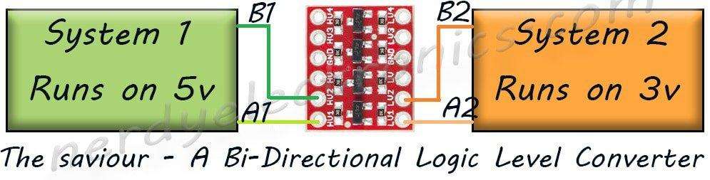
- System 1 has two signals – A1(output) and B1(input)
- System 2 has two signals – A2(input) and B2(output)
A1 and B1 are 5 volt signals and A2 and B2 are 3 volt signals. Furthermore, A1 connects to A2 and B2 connects to B1.
We connect A1 to HV1 pin of the level converter and A2 to the LV1 pin. Similarly B1 pin to HV2 pin of the level converter and B2 pin to the LV2 pin.
Since A1 is output and A2 is input, any 5v signal on A1 will reflect as 3v on A2. Similarly, a 3v signal on B2 will be read as 5v signal on B1.
Thus, we have successfully interfaced two systems working on two different voltage levels.
Interfacing a USB to TTL converter with ESP8266
This is exactly how the ESP8266 is interfaced with a computer through a USB to TTL converter. The USB to TTL converter operates at 5v and the ESP8266 operates at 3.3v. In our example, the USB to TTL converter is system1 and the ESP8266 is system2. The only difference is that the ESP8266 operates at 3.3v instead of 3v.

In the above circuit, we have to connect RXD from the USB to TTL converter to Tx of ESP8266 and TXD from USB to TTL converter to Rx of ESP8266.
Hi, I’m Vivek, a Senior Embedded Innovation Specialist. I have been working on Embedded Systems and IoT for the past 11 years. I love to share my knowledge and train those who are interested. Nerdyelectronics.com was started out of this interest. You can read my full profile in this link.


 Update in ESP8266")

I just got a set of these 4 channel LLC converters to shift 3.3v signal output of a NodeMCU to a variety of 5v devices I’ve used previously with an Arduino. As the NodeMCU is very sensitive to voltage I thought I’d use a multi-meter to make sure the voltages coming out of the LLC are OK. I powered each side of the LLC then applied 3v to one of the low level channels and measured the voltage in the matching high level side. But it seems every pin in both sides of the LLC are always set high. That is regardless of any voltage applied to any of the channels *all* pins on the 3.3v side are 3.3v and all in the 5v side are 5v. I assumed it was a faulty unit so soldered up another one and got the same result. Is this a symptom of measuring these with a multi-meter? It just doesn’t seem right. I’d have thought channels are 0v unless powered by an input. Is this right or have I got a faulty batch of converters?
Hi Simon
Sorry for the late reply. Why don’t you try this – Using a multimeter check if there is any short between the pins. There is the continuity test option in most miltimeters. If you select that option and put the multimeter probes on two ends of a wire, it will beep if the wire is not broken. If you connect the probes between two points and if there is a beep, it means that those two points are somehow connected.
Before you solder the pins, check on the pads. There shpuld not be any connection and there shpuld not be any beep. If you get a beep means that the unit is faulty.